Light Ring
I recently got around to finally implementing an LED "glowing" effect originally described to me when I was an intern in college: when using a PWM to control the brightness of an LED, you can make the LED slowly glow on and off by modulating the duty cycle with a sine wave. This was also a nice, small project to get familiar with the Microchip (nee Atmel) SAM D10/D11 Xplained-mini eval board that I picked up a while back from Digikey. It had been sitting idle on my desk at home, so I thought I'd spent a Sunday morning spinning it up.
The success of that experiment led me to think about a more elaborate lighting arrangement. Due to the unrelated success with paste + hot air soldering on the Bit1 I/O respin, I also wanted to try using a QFN package for something. So now I've whipped up three new boards (modules):
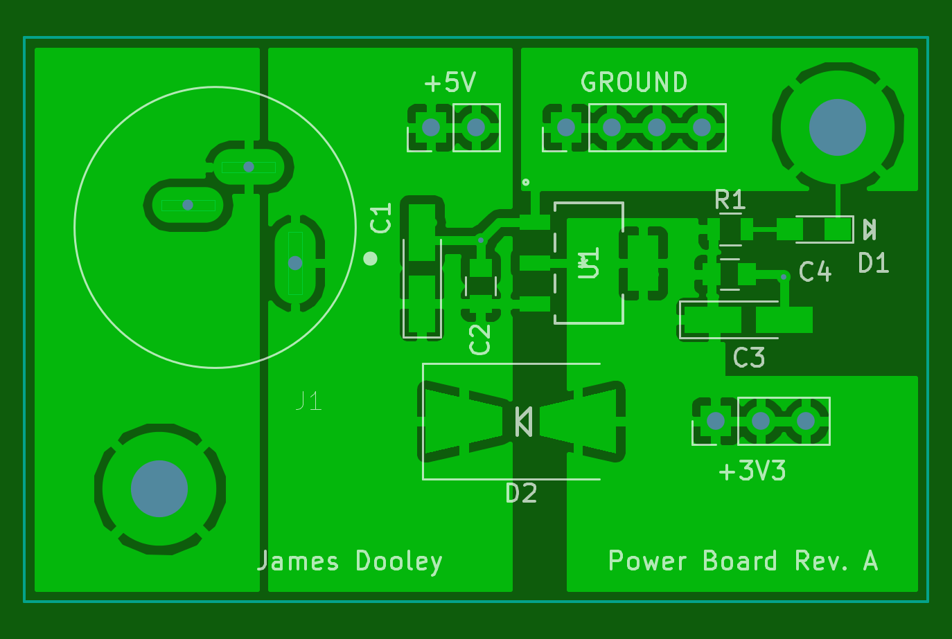
- Power Board: barrel connector input (from wall wart), +3.3v linear regulator, 0.1" header outs
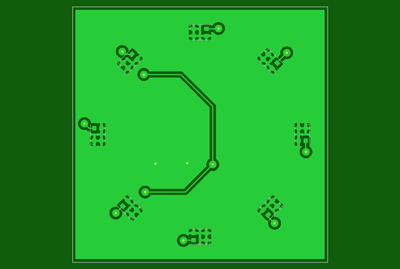
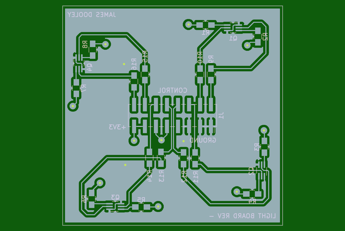
- Light Board: 8x LEDs arranged in a ring
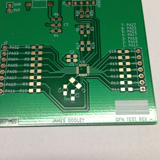
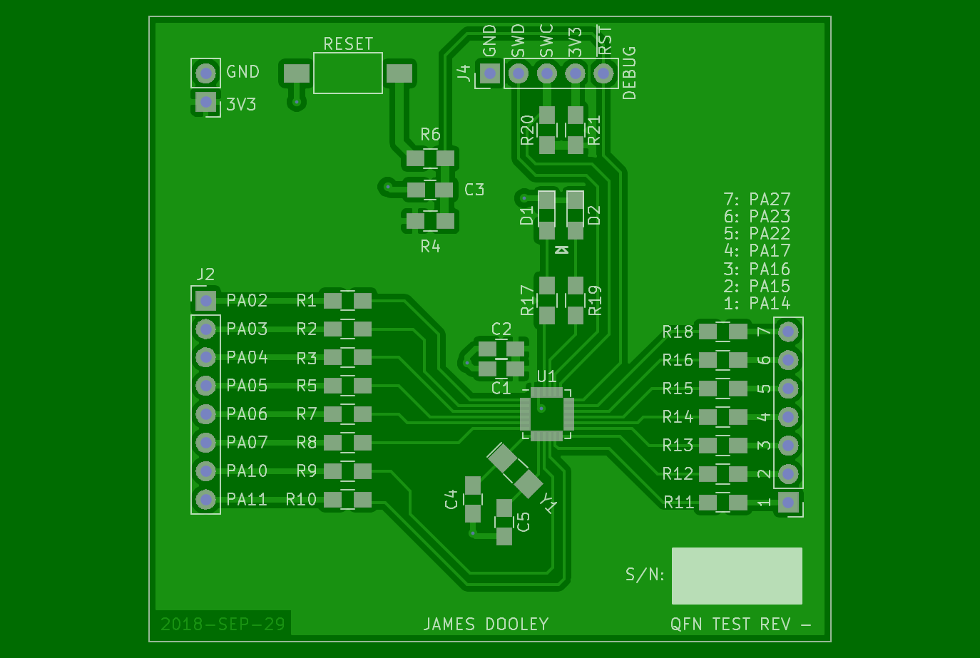
- QFN Test Board: SAM D11 in 24-pin QFN with 0.1" headers on the I/O pins
The Power Board will be a generic reusable module for all future boards that run off 3.3 volts. I have a little +5 volt / 1 amp wall wart that ends in a barrel connector. Why a linear regulator, not a switcher? My background in software-defined radios has taught me that I don't need switching noise running around inside my systems. Point-of-load linear regulation after the switcher provides cleaner power and fewer problems. Why am I saying linear regulator instead of LDO? Because I'm using some AMS1117 linear regulators that I snagged off AliExpress. Any regulator with more than a volt of drop-out can't really be considered low drop-out. I've included a power LED on the board for two reasons: positive assurance of output power, and to provide a guaranteed minimum load to the regulator to ensure it starts and provides consistent regulation.
The Light Ring board is an experiment in understanding how bright LEDs can be and using FETs as load switches. I don't have a good understanding of how bright 2,100 millicandela is, so I'm building a board to find out. I learned about using FETs as load switches from the Hardware Engineers at work, and that seems important in this application so that I'm not trying to draw 40 mA directly from each of eight microcontroller pins simultaneously.
The QFN Test board holds a 24-pin QFN SAM D11 microcontroller, a couple LEDs for diagnostics, a SWD header, and I/O pin headers. Just enough support to test out whether the I'm able to successfully solder a QFN package with stencil and paste.
All three schematics are complete, layout is done, and gerbers are generated. Boards were built using Seeed Studio's Fusion PCB service. Small two-layer boards are awfully cheap from them. The QFN board has an ENIG finish for improved solderability, but the other two boards live on HASL. I run a 63/37 no-clean process at home.